High availability clustering on a budget with KVM
Virtual Cluster
Cluster systems serve many different roles. Load-balancing clusters help distribute the load evenly among the various systems. High-performance clusters (HPCs) focus on maximizing the computer performance. The clustering alternative known as a High-Availability (HA) cluster attempts to maximize availability. If one system fails, the service running on it simply migrates to another cluster node, and the users will not even notice the failure.
With the rise of virtualization, virtual machines are increasingly deployed in clustering configurations – including in HA environments. This article describes how to set up an HA cluster, which could serve as a fail-safe web or mail server system. Instead of making individual services highly available, cluster managers create and monitor the complete virtual machine instances that provide high availability.
The virtual clustering configuration looks as if the physical host systems have a collection of virtual machines. All of the virtual machines run in a shared storage area accessible by all host systems. This storage area could consist of iSCSI or Fibre Channel (FC) storage, but an NFS export will do for test purposes (although the performance with NFS leaves much to be desired).
The cluster manager checks at regular intervals to ensure that individual host systems are available, using a variety of methods. For example, the cluster nodes might be expected to send a heartbeat across the network at regular intervals. Alternatively, some implementations store status messages or run heuristics, such as pinging a central router.
If the vital signs from a cluster node are missing, the cluster manager will take remedial action, such as restarting a downed system. This procedure is known as fencing (formerly referred to as STONITH – Shoot The Other Node In The Head). Fencing is necessary to avoid a cluster node trying to access what used to be its resources after another node has taken over responsibility for them. (See the box titled "Fencing.")
A cluster manager can also migrate systems online. This migration feature is really useful if you need to perform some maintenance on one of the servers. In this case, all the virtual systems on the cluster node are migrated to another node. The user doesn't even notice that the virtual systems have moved and just carries on working.
Choosing a Hypervisor
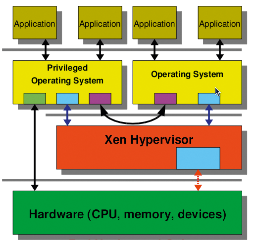
Before you can run virtual machines as a cluster service, the administrator has to find a suitable hypervisor (the intermediary between virtual machines and physical hardware). If you are interested in a virtual cluster on a limited budget, two open source virtualization systems for Linux include Xen (Figure 1; see the "The Xen Option" box) [1] and KVM (Figure 2) [2].


The implementation described here uses KVM, a third-generation hypervisor that is by now the de facto standard for open source virtualization solutions on Linux. KVM made the grade for the official Linux kernel so quickly because of its excellent code quality and because it supports all of today's virtualization technologies, such as IOMMU (secure PCI pass-through), KSM (shared memory management), and VirtIO (paravirtualized I/O drivers). This means that virtual operating system instances will run with nearly native performance. However, KVM does need a state-of-the-art CPU generation with virtualization functionality (VT-X/AMD-V). All the virtual machines in this article will run on the KVM hypervisor. Current enterprise solutions for the virtualization of servers and desktops [3] are all based on KVM.
Setup and Software
The example discussed in this article uses two physical nodes: host1 and host2. Both physical nodes use Red Hat Enterprise Linux 5 (RHEL5); however, all of the examples will work with current no-cost Fedora systems. Each of the hosts also has a virtual KVM system instance (vm1, vm2). These systems run on Fedora; however, the setup would work with any other operating system that the KVM hypervisor supports [4].
In testing, I decided to do without installing more virtual machines to avoid making the setup unnecessarily complex. Depending on its hardware resources, a physical host can obviously accommodate many virtual instances. The back end for the virtual machines are clustering-capable logical drives, which you need to mount statically on the cluster hosts. An iSCSI (Internet Small Computer System Interface) server acts as the storage back end. This low-budget approach is an alternative to traditional SAN solutions with Fibre Channel, but it will work without affecting performance at today's Internet bandwidths.
The cluster manager in this example is Red Hat's own cluster suite (RHCS). It contains everything I need to run an HA cluster. Besides the OpenAIS-based cluster manager, cman, the cluster configuration system ccs ensures a standardized configuration of the individual nodes. Fencing agents are responsible for failed nodes, and the Resource Manager rgmanager is responsible for the HA services proper; that is, the virtual machine instances in this example. The Cluster Logical Volume Manager (CLVM) is used to mount the shared storage.
Architecture
The two physical cluster nodes in this article each have four network cards: eth0 through eth3. The first (eth0), and third (eth2) network cards are bonded using a virtual bonding device bond0. This device is connected to a public network by means of a bridge br0. This network supports access to the individual applications on the virtual machines. A second bonding device, bond1, comprises the second (eth1) and fourth (eth3) network cards. This bonding device is part of the private cluster network – the network used to handle cluster communications between the individual nodes. This includes communications with the individual fencing agents and network traffic to the iSCSI server. The network cards must be bonded to prevent them from becoming a single point of failure (SPoF). It wouldn't make much sense to design the systems for high availability yet risk losing the whole setup if a network card failed.
The kernel-bonding driver on Linux provides a tried-and-trusted solution for this. It lets you group multiple network cards to create a new virtual device. Depending on the bonding mode, the traffic will use a round-robin approach or a master/slave model for the individual cards. To access the iSCSI server, you alternatively can use the Linux kernel device mapper's multipathing function. As with bonding, many roads lead to Rome. If one path fails, access to the data is still possible via the remaining paths.
The back-end storage for the virtual machine instances can be either image files or block devices on a shared data medium. Block devices in the form of logical drives as provided by the CLVM are preferable. Compared with image files or raw devices, logical drives offer the benefit of not causing additional overhead on the cluster filesystem. Additionally, CLVM has a snapshot function that is useful for backing up virtual machines.
The CLVM configuration is more or less identical to that for the individual systems. CLVM handles file lock information differently. CLVM is also responsible for synchronizing this information between the individual nodes in the cluster. This notifies each system of data storage access by the other systems. To configure this, install the lvm2-cluster package on all the nodes in the cluster. Then you can run lvmconf to enable the locking libraries (Listing 1). If you use CLVM, you need to enable cluster-wide locking (Type 3). Local file locking (Type 1) is the standard setting for LVM.
Listing 1: Locking Level 3 for CLVM
01 # lvmconf --enable-cluster
02 # grep locking_type /etc/lvm/lvm.conf
03     locking_type = 3
Configuration
Before configuring the virtual systems, you'll need to set up the iSCSI system. iSCSI is a method defined in RFC 3720 that transfers legacy SCSI commands over a TCP/IP network. The legacy SCSI controller initiates this, and the storage medium is the target. The advantage of iSCSI is that you can run large-scale storage networks on the existing infrastructure.
TCP/IP offload cards that reduce the load on the CPUs in the machines could be useful here. Alternatively, you could rely on dedicated iSCSI hardware, although it is not cheap. For initial testing, you will probably want to experiment with your existing hardware. Linux has a scsi-target-utils package for the server setup, and you will typically be able to download it from your distributor's repositories.
After installing the package, you need to create a block device on the iSCSI server and make the device available to the clients via the iSCSI protocol. Ideally, you will be using redundant hardware for this device; otherwise, the exported disk is another single point of failure. With just a couple of commands, shown in Listing 2, you can configure the iSCSI server.
Listing 2: Configuring the iSCSI Server
01 # chkconfig tgtd on; service tgtd start
02 # tgtadm --lld iscsi --op new --mode target --tid 1 -T iqn.2008-01.com.example:storage.iscsi.disk1
03 # tgtadm --lld iscsi --op new --mode logicalunit --tid 1 --lun 1 -b /dev/sda
04 # tgtadm --lld iscsi --op bind --mode target --tid 1 -I ALL
The first command here creates the iSCSI target, which is identified by means of a unique ID and a name. Clients use this ID to access the target later on. The next step is to assign one or multiple local block devices on the server to the target. Finally, you can use Access Control Lists (ACLs) to restrict access to the server. In this example, any computer can access the server. If this works, calling tgtadm should list the finished configuration (Listing 3).
Listing 3: iSCSI Server Setup
01 # tgtadm --lld iscsi --op show --mode target
02 Target 1: iqn.2008-01.com.example:storage.iscsi.disk1
03         System information:
04         Driver: iscsi
05         Status: running
06     I_T nexus information:
07     LUN information:
08         LUN: 0
09             Type: controller
10             SCSI ID: deadbeaf1:0
11             SCSI SN: beaf10
12             Size: 0
13             Backing store: No backing store
14         LUN: 1
15             Type: disk
16             SCSI ID: deadbeaf1:1
17             SCSI SN: beaf11
18             Size: 500G
19             Backing store: /dev/sda
20     Account information:
21     ACL information:
22         ALL
Network Bonding
To prevent the network cards and thus the connection to the cluster and storage network from becoming a single point of failure, you need to aim for a redundant design. Ideally, each network card should be connected to a different switch to prevent a switch failure from compromising availability. On Linux, the kernel's bonding module is typically used to link network cards. This setup uses master/slave mode instead because it removes the need for a special network switch configuration and it will still survive a card failure. Listing 4 shows an example of the configuration for the first network card in /etc/sysconfig/network-scripts/ifcfg-eth0. The other cards in the same bond are configured in a similar way.
Listing 4: ifcfg-eth0
01 DEVICE=eth0
02 ONBOOT=yes
03 USERCTL=no
04 SLAVE=yes
05 MASTER=bond0
Listing 5 shows the /etc/sysconfig/network-scripts/ifcfg-bond0 configuration for the bonding device. To set the required mode, use the BONDING_OPTS command. A detailed description with all the configuration options for the bonding driver resides in the kernel documentation folder (/usr/share/doc/kernel-doc/Documentation/networking/bonding.txt).
Listing 5: ifcfg-bond0
01 DEVICE=bond0
02 IPADDR=192.168.10.200
03 NETMASK=255.255.255.0
04 ONBOOT=yes
05 USERCTL=no
06 BONDING_OPTS="mode=1 miimon=100"
When the system is running, the /proc/net/bonding/bond0 file gives you useful information on the status of the device and its slaves.
Cluster Node Configuration
What applies to the iSCSI server also applies to the cluster nodes themselves. To avoid a SPoF on the network, you must bond the network cards for the public network (eth0/eth2) and the cards for the cluster and storage network (eth1/eth3) to create virtual bond devices. The configuration is the same as the bonding configuration for the iSCSI Server .
To make the exported iSCSI device available on the cluster systems, install the iscsi-initiator-utils package. For most distributions, this package is available in the standard software repositories. The commands shown in Listing 6 let you access the exported iSCSI target.
Listing 6: ifcfg-bond0
01 # chkconfig iscsi on; service iscsi start
02 # iscsiadm -m discovery -t st -p 192.168.10.200
03 iqn.2008-01.com.example:storage.iscsi.disk1
04 # iscsiadm -m node -T iqn.2008-01.com.example:storage.iscsi.disk1 -p 192.168.10.200 -l
iSCSI discovery creates all the targets on the specified server before logging in to the server in the next step. After this step, the exported device is available locally. A call to fdisk -l should list the iSCSI device in addition to the local device.
The Linux device mapper's volume group will rely on the device later. In typical LVM style, the following commands are used for the configuration step:
# pvcreate /dev/sdb1
# vgcreate vg_cluster /dev/sdb1
# lvcreate -n lv_vm1 -L 50G vg_cluster
# lvcreate -n lv_vm2 -L 50G vg_cluster
The first command deposits the required LVM signature on the first partition of the mounted iSCSI device. The next step is to run vgcreate to create the vg_cluster volume group, which comprises the individual devices. Finally, lvcreate creates the logical drives, which will serve as back ends for the virtual machine instances later on. To make the logical drives created here available to all the cluster nodes, start the clvmd service on each node. However, you'll need to set up the cluster before doing this.
Cluster Setup
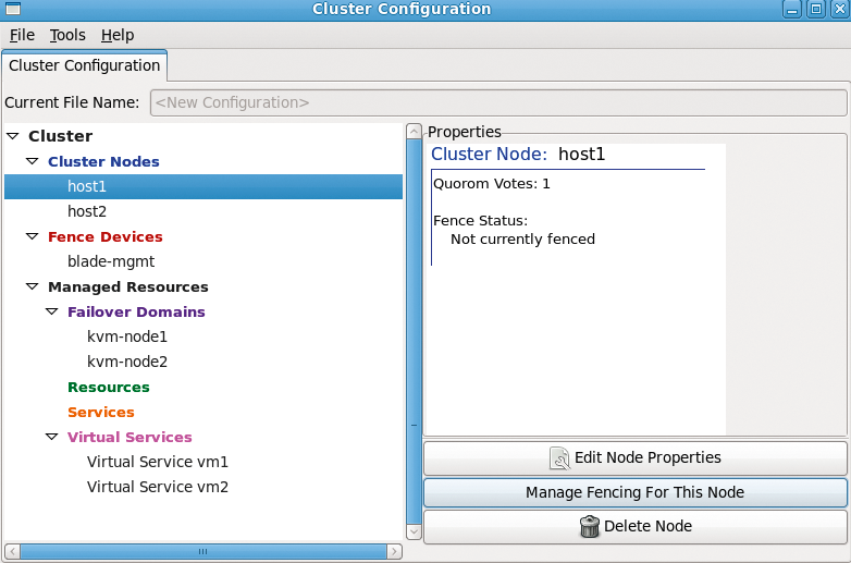
The HA cluster can be set up several ways. system-config-cluster (Figure 4) and Conga are two graphical applications; however, you can easily create an XML-based configuration file manually and configure the cluster using this approach. Not many options are available for the graphical tools, making it necessary to edit the file in most cases. Listing 7 shows an example of a cluster configuration file.
Listing 7: /etc/cluster/cluster.conf
01 <?xml version="1.0"?>
02 <cluster alias="dom0cluster" config_version="1" name="examplecluster">
03  <fence_daemon clean_start="0" post_fail_delay="0" post_join_delay="30"/>
04  <clusternodes>
05  <clusternode name="host1-cluster.example.com" nodeid="1" votes="1">
06  <fence>
07  <method name="1">
08  <device name="balde-mgmt.example.com" blade="1"/>
09  </method>
10  <method name="2">
11  <device name="manual" nodename="host1.example.com"/>
12  </method>
13  </fence>
14  </clusternode>
15  <clusternode name="host2-cluster.example.com" nodeid="2" votes="1">
16  <fence>
17  <method name="1">
18  <device name="blade-mgmt.example.com" blade="2"/>
19  </method>
20  <method name="2">
21                     <device name="manual" nodename="host2.example.com"/>
22                </method>
23             </fence>
24         </clusternode>
25     </clusternodes>
26     <cman>
27         <multicast addr="225.0.0.250"/>
28         <expected_votes="1" two_node="1"/>
29     </cman>
30     <fencedevices>
31         <fencedevice agent="fence_bladecenter" ipaddr="192.168.10.100" login="fence" name="blade-mgmt" passwd="redhat"/>
32         <fencedevice agent="fence_manual" name="manual"/>
33     </fencedevices>
34
35 <!--
36     <rm>
37        <failoverdomains>
38            <failoverdomain name="kvm-node1" ordered="0" restricted="0">
39                 <failoverdomainnode name="host1-cluster.example.com" priority="1"/>
40            </failoverdomain>
41            <failoverdomain name="kvm-node2" ordered="0" restricted="0">
42                    <failoverdomainnode name="host2-cluster.example.com" priority="1"/>
43            </failoverdomain>
44        </failoverdomains>
45        <resources/>
46        <vm name="vm1" domain="kvm-node1"/>
47        <vm name="vm2" domain="kvm-node2"/>
48        <vm name="vm3" domain="kvm-node1"/>
49        <vm name="vm4" domain="kvm-node2"/>
50     </rm>
51 -->
52 </cluster>

The configuration file includes several sections, starting with the individual cluster nodes. Make sure the internal cluster network can resolve the hostnames used here; otherwise, cluster communications will be routed over the public network. For each node, you must specify a fencing method. Because this example uses a blade center, it makes sense to use its own blade management system as the primary emergency cut-off system. Manual fencing is configured as the backup method. The cluster manager is based on the OpenAIS framework. Its heartbeat signals involve sending a token back and forth between the cluster nodes with the use of multicasting. If your switches can't use the default multicast address, change it.
The next thing to do is specify the fence devices – in this case, the IP addresses and login credentials for the blade management system. A list of supported fence devices is available [5]. If you want a virtual system to run primarily on one specific cluster node, you can use failover domains to implement this. This mechanism is useful in preventing all of your virtual machines from running on the same system, especially if you are running multiple systems.
The final section is for the resource manager. Here, you need to add the name of each virtual machine instance. If you are using the Xen hypervisor, you'll also need to specify the path to the configuration file here. Xen can store this at a location that is accessible to all nodes. KVM doesn't have this capability right now. Instead, you will need to store the configuration files for the virtual machines on the local filesystems and then synchronize between the individual cluster nodes. The cluster suite will add support for shared storage of the configuration files in the near future. Because the virtual machines don't exist at this stage, the section with the configuration file is still commented out.
After modifying the configuration file to reflect your environment, you can distribute it to all the cluster nodes – using scp, for example. Once the cluster is running, you can run ccs_tool update /etc/cluster/cluster.conf to do this. The important thing is to increment the configuration file version number after each change; otherwise, the cluster manager will not notice any changes to the file. Once all the cluster nodes have the file, you can start cluster operations by typing service cman start. The cluster-aware CLVM is now functional and can be launched by typing service clvmd start. A call to clustat should now confirm that both nodes are active cluster systems.
Before you start configuring the virtual machines, you still need to set up the network environment. Because the virtual machines will share a network with the cluster systems, you will need a bridge here. To configure the bridge, see the description in the "Bridge for the Public Network" box.
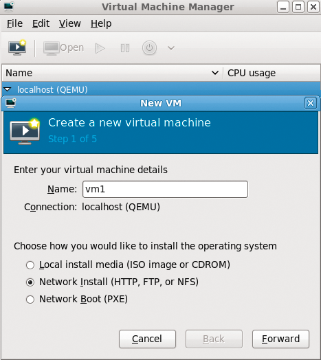
Of the several approaches available to create the virtual machine instances, you can use virt-manager (Figure 5), a graphical application, or the virt-install command-line tool, which supports many possible configuration options, as the call for setting up the first virtual machine shows (Listing 8).
Listing 8: virt-install
01 # virt-install \
02   --network bridge:br0 \
03   --name vm1 \
04   --ram 1024 \
05   --disk path=/dev/vg_cluster/lv_vm1 \
06   --location http://192.168.0.254/pub/os/fc12/ \
07   --nographics \
08   --os-type linux \
09   --os-variant fedora12 \
10   --extra-args 'console=xvc0 ksdevice=br0 \
11   ks=http://192.168.0.254/pub/ks/vm1.cfg'

Specifying a kick-start file is optional. Also, you can provide all the configuration instructions for the systems to install manually. It is important to specify the bridge created in a previous step, br0, and the logical drive, lv_vm1, on the iSCSI server. This will now serve as the storage back end for the virtual machines. The XML-based configuration file for a virtual machine created in this way is stored in the /etc/libvirt/qemu/ directory on the local machine. This file needs to be synchronized between all the cluster nodes; for this example, this means between host1 and host2.
Now it's time to enable the cluster configuration in the final section of the file. To do so, remove the pound signs and then type ccs_tool update to transfer the configuration file to all the other nodes in the cluster. Don't forget to increment the version number for the file. service rgmanager tells the manager to get to work.
Because the cluster resources manager relies on SSH to migrate the virtual machines, you need to create a keyring for each cluster node. Make sure you avoid assigning a passphrase when creating the key. Then, simply run ssh-keygen to generate a key (Listing 9).
Listing 9: ssh-keygen
01 # ssh-keygen -f /root/.ssh/id_rsa_cluster
02 Generating public/private rsa key pair.
03 Created directory '/root/.ssh'.
04 Enter passphrase (empty for no passphrase):
05 Enter same passphrase again:
06 Your identification has been saved in /root/.ssh/id_rsa_cluster.
07 Your public key has been saved in /root/.ssh/id_rsa_cluster.pub.
08 The key fingerprint is:
09 bb:0f:e3:7f:3e:ab:c3:5d:32:78:85:04:a2:da:f1:61 root@host1
You need to distribute the public part, that is the /root/.ssh/id_rsa_cluster.pub file, to all nodes in the cluster. The StrictHostKeyChecking option must be disabled for all the cluster nodes in the SSH client configuration file, /root/.ssh/config (Listing 10).
Listing 10: /root/.ssh/config
01 Host host*
02     StrictHostKeyChecking no
03     IdentityFile /root/.ssh/id_rsa_cluster
All the steps listed here – that is, modifying the configuration file, generating the SSH keys, and distributing the keys – must be performed on all the cluster nodes. After doing so, you should be able to use SSH to log in as root on any cluster node, and from any cluster node, without supplying a password. If this is not the case, you will have some troubleshooting ahead of you; otherwise, your cluster will not work properly.
Resource Manager
After completing all this preparatory work, you can enable the individual virtual machines via the cluster manager. The tool clusvcadm brings the virtual machines to life:
# clusvcadm -e vm:vm1 -m host1.example.com
# clusvcadm -e vm:vm2 -m host2.example.com
The output from clustat should now show you the two virtual systems (Listing 11).
Listing 11: clustat
01 # clustat
02 Member Status: Quorate
03
04   Member Name                                ID   Status
05   ------ ----                                ---- ------
06   host1.example.com                          1 Online, Local, rgmanager
07   host2.example.com                          2 Offline
08
09   Service Name         Owner (Last)                         State
10   ------- ----         ----- ------                         -----
11   vm:vm1               host1.example.com                    started
12   vm:vm2               host2.example.com                    started
If one system fails, the virtual systems running on it will start up on the other host. Online migration is also possible. To do this, call clusvcadm as follows:
# clusvcadm -M vm:vm1 -m host2.example.com
For demonstration purposes, consider the following scenario: vm1 is currently compiling the Linux kernel. During the compilation process, the above-mentioned command is entered to migrate the virtual machine to the other host. The migration is totally transparent for the user.
The current setup would let you add a second cluster on the virtual machines. This could handle the individual networking services on the virtual machine. The setup is more or less identical; however, when configuring the (virtual) fence devices, you need to use the special fence_virt agent. This passes the required instructions to fence_virtd if one of the virtual machines fails to respond.
Conclusions
A cluster setup using virtual machines as cluster resources is easily set up. Compared with a native live migration based on Libvirt, the cluster manager will also migrate machines whose host system has failed. This migration is totally transparent for the user and does not require manual intervention. Even though I only used Linux-based virtual machines in this article, you can run different operating systems on the virtual machines.
