Redundant network connections with VMware ESX
Backup Management
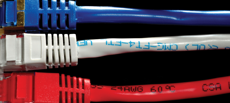
VMware offers numerous functions to ensure maximum failure protection and availability in a server landscape. However, this functionality mainly just takes the server hardware, and thus the CPU, RAM, and storage components, into consideration. In many cases, administrators forget that a network failure will make the virtual servers inaccessible. A switch should never be a single point of failure (Figure 1).

A sophisticated network concept is a must-have for running an ESX farm. One option is a redundant network connection using two switches, but you should not forget to include the central storage in this – whether you use iSCSI or Fibre Channel.
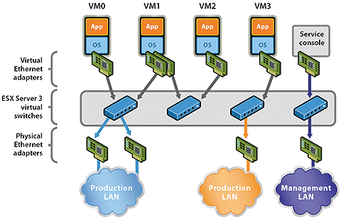
The physical network adapters in the ESX servers, which are connected to the switches on the network, are linked by VMware within the ESX server by means of virtual switches (vSwitch). Various connection types can run on a vSwitch, as shown in Figure 2:
- Service Console Port: The service console is the management interface that supports administration via the vSphere client (or VI client in ESX3.x).
- VMkernel Port: The ESX server uses a VMkernel port to access, for example, IP storage (iSCSI, NFS). Communications between multiple ESX servers, such as vMotion, also use this port.
- Network for virtual machines: This connection type connects the virtual machines with the physical network and is also used for the internal communications between multiple virtual servers on the same ESX host without stressing the physical network.

Administrators need to create port groups for virtual machines on a virtual switch. The port groups are typically created to match the existing VLANs, which support segmentation of the physical network. This setup gives the virtual servers access to the available networks.
Which Switch?
How you implement the network design for your own ESX farm depends greatly on the characteristics of the LAN, on the hardware you use for the ESX servers, and, thus, on the available physical network adapters. To avoid compromising performance and security, you should have separate virtual switches for the service console, the virtual machine network, and any IP-based storage.
In many cases, you will not have enough physical NICs to implement a redundant connection for each connection type – you would need at least six ports. Thus, you will need to consider carefully which connection types can do without redundancy or where you are prepared to accept the risk. However, note that for two connection types, VMware itself recommends running parallel vSwitches.
Most administrators choose to bind two physical network adapters to one virtual switch. VMware calls this NIC teaming. The term used by IEEE is link aggregation, defined in IEEE 802.1ax (formerly 802.3ad). Besides VMware, most vendors use proprietary terms to describe link aggregation, including terms such as EtherChannel, trunking, bundling, teaming, or port aggregation.
Link Aggregation
Link aggregation refers to the parallel bundling of multiple network adapters to create a logical channel. This technology offers two major benefits compared with legacy wiring with a single network cable: higher availability and faster transmission rates. As long as at least one physical link exists, the connection will stay up, although the bandwidth will drop.
Basically two different approaches can be used: static link aggregation and dynamic link aggregation. The static method entails choosing an algorithm when you set up the link by choosing the port on the basis of the source or target IP address, or both, or source or target MAC, or both. The IEEE-compliant LACP and multiple proprietary solutions (e.g., PAgP by Cisco or MESH by HP) are based on dynamic linking. Differences between the protocols are marginal, but VMware ESX 4 only supports static link aggregation with the IP source/target algorithm [1].
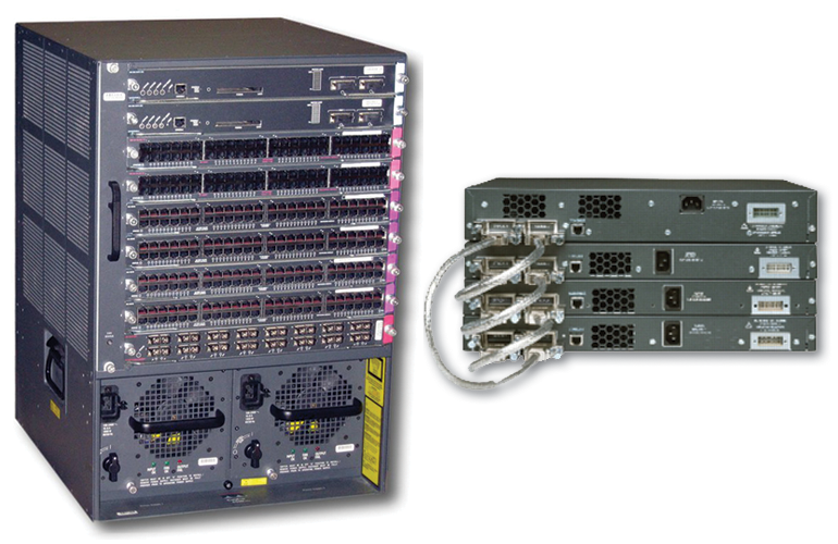
You cannot bundle ports over multiple switches, which typically leaves you with two approaches to ensuring maximum failure protection: You use either modular or stack switches (Figure 3).

Modular switches work like a blade center with a chassis that is typically powered by redundant power supplies and has several slots for network ports. A switch stack involves using switches that all have separate cases and power supplies, but which can be connected by special stack cables and then managed as a single device. The individual switches in a stack typically don't have redundant power supplies, but creating a stack can still provide redundancy and thus a flexible solution, just like chassis-type devices.
To connect an ESX server to the network with two wires, you need to configure both the ESX server and the switch correctly. If you'll be bundling two ports on a Cisco switch, the configuration in Listing 1 is all you need.
Listing 1: Cisco Configuration: Bundling Two Ports
interface GigabitEthernet1/1
channel-group 1 mode on
switchport trunk encapsulation dot1q
switchport mode trunk
no ip address
!
interface GigabitEthernet2/1
channel-group 1 mode on
switchport trunk encapsulation dot1q
switchport mode trunk
no ip address
!
interface Port-Channel 1
switchport trunk encapsulation dot1q
switchport mode trunk
no ip address
Multiple Modes
Cisco supports multiple channel group modes. The mode used here, on, simply enables EtherChannel and thus static link aggregation. The other modes are active (LACP in active mode), passive (LACP in passive mode), auto (PAgP in passive mode), and desirable (PAgP in active mode).
With LACP and PAgP, active mode refers to the interface starting to transmit packets to find a counterpart that is in active or passive mode, and that responds to the packets to set up link aggregation. In passive mode, the interface simply waits for packets from the other end; thus, both ends cannot use passive mode. Ideally, you should set one end to be active and the other to use passive mode to avoid sending unnecessary packets. The use of active mode at both ends is supported, however.
Because ESX only uses static link aggregation on the basis of the Src-Dst-IP algorithm, you need to tell the switch to use the same algorithm. The show etherchannel balance command shows which algorithm is currently in use (Listing 2).
Listing 2: Show etherchannel
Switch#show etherchannel load-balance
EtherChannel Load-Balancing Configuration:
        src-mac
EtherChannel Load-Balancing Addresses Used Per-Protocol:
Non-IP: Source MAC address
  IPv4: Source MAC address
  IPv6: Source MAC address
By default, the sender-side MAC address decides which physical port to use. All frames from a source MAC always use the same interface. The following command tells the switch to use the algorithm supported by ESX:
Switch#port-channel load-balance src-dst-ip
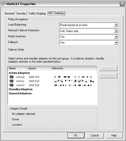
On the ESX server side, you need to create a virtual switch comprising two active network adapters that are connected with the switch. In the vSwitch properties, you need to make sure that ESX can only route for load balancing on the basis of the IP hash; you will need to modify the properties to do so (Figure 4). In this load-balancing mode, ESX uses a hash to determine which uplink adapter to use for each packet. To calculate this, ESX refers to the IP source and target addresses. All the other modes either do not provide genuine load balancing or do not support genuine failover.

When you implement load balancing on the basis of the IP hash, VMware recommends that you only use the link status for failover detection and do not configure any standby adapters.
Conclusions
Administrators face some easy decisions when planning redundant network connections for ESX servers, because the list of options is fairly short. VMware has limited support for this functionality, which I hope will change in future releases. However, the good news is you can improve network availability for your ESX farm with little effort and a modicum of networking knowledge.
