Link aggregation boosts securityand increases throughput
Thick Wires
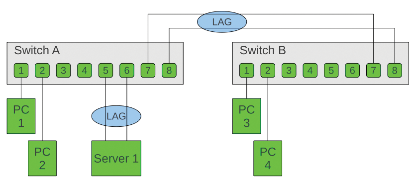
Link aggregation means grouping connections to link multiple connections between two components (switches, servers, storage systems, etc.) and view them logically as a single connection (Figure 1). As a rule, a system administrator would use this solution to combine two to four individual connections, which are then no longer considered individual links but a link aggregation group (LAG). Although most managed switches support link aggregation, you should look at the data sheet to be sure. The same is true for IP-based iSCSI and NFS/CIFS storage systems. Servers need at least two network cards and software support from the operating system or the network card driver for link aggregation.

Conditions
Before multiple links can be grouped in a LAG, some prerequisites must be met. All links must
- be in full duplex mode,
- have the same data rate (usually 1 Gbps),
- be parallel point-to-point connections
- always terminate on exactly one switch or server at the end points.
Aggregation with multiple switches on one end, such as split multilink trunking (SMLT) by Nortel, is not possible with link aggregation. The exception is with virtual switches, which comprise several physical switches but act as a single switch, such as the Cisco Virtual Switching System 1440 or the Juniper Virtual Chassis from the 3000/4000 series.
Resiliency
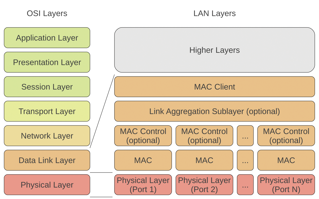
In the network stack, the link aggregation sublayer resides within the data link layer – to be more precise, between the MAC client and MAC sublayers (Figure 2). If one connections in a LAG fails, the distributor automatically spreads the traffic from the broken connection to another connection in the link aggregation. As long as at least one physical connection is present, the LAG connection stays up.

Increased Bandwidth
Because 10Gb network components are still relatively expensive, bundling of several 1Gb connections in a LAG is a cost-effective alternative wherever high bandwidth is required. However two 1Gb links in a LAG does not automatically mean a capacity of 2 Gbps is available for exchanging data between two computers.
A single Ethernet frame is only transferred via a single link, despite link aggregation. According to the IEEE 802.1AX-2008 standard [1], the order of the frames in a conversation between two terminals cannot be changed. This is easily ensured if all the frames in a conversation are sent exclusively on the same individual link. However, if two servers in a LAG comprising two 1Gb connections are connected directly to one other, copying a file from one server to the other will not happen at more than 1Gbps.
However, multiple, parallel conversations can be distributed across the links in a LAG; in this case, you will benefit from a larger potential bandwidth. This method allows for simple implementation in switches and servers. Because it does not require additional buffers, no latency increases are attributable to link aggregation.
Load Balancing
How does a switch or a server choose a specific link to transfer data from a conversation? The standard assigns that task to a so-called frame distributor. There are no hard and fast rules for how the frame distributor distributes the data. The only requirement is that of limiting a conversation to a single link.
Most switches and operating systems use the MAC addresses of the sender and the recipient, or their three or six least significant bits, to select the link. An example this kind of selection is shown in the "MAC-Based Load Balancing" box.
Static or Dynamic?
In static link aggregation, all of the configuration parameters are stored only once on both components involved in the LAG. As long as one link in a LAG is up, this link is also used for data transfer in static link aggregation. If media converters are used, it can happen that the link on the switch is up, but the connection to the switch at the other end is interrupted. In this case, the switch still sends data via this connection, and the data transfer is thus interrupted.
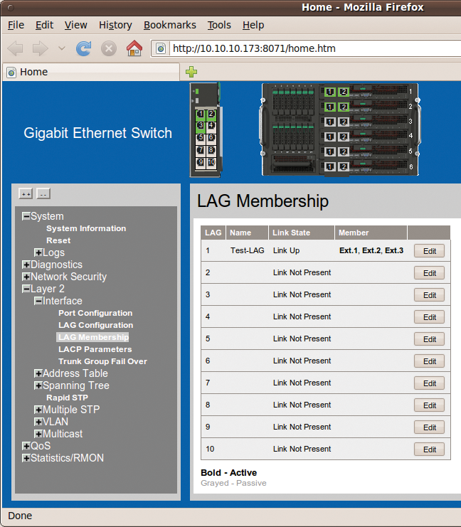
For more control, it is a good idea to use dynamic link aggregation with the Link Aggregation Control Protocol (LACP), which supports the exchange of information about link aggregation between the two parties involved (Figure 3). This information is packaged in LACPDUs (LACP Data Units). Each individual switch port in a dynamic LAG can be configured as an active or passive LACP:
- Passive LACP: The port prefers not to transfer any LACPDUs. The port only sends LACPDUs if the remote site is an active LACP (i.e., it prefers not to speak unless spoken to).
- Active LACP: The port prefers to transfer LACPDUs and thus to speak the protocol – regardless of whether the remote station is a passive LACP (i.e., it prefers to speak regardless).
Compared with static link aggregation, dynamic link aggregation with LACP offers the following benefits:
- The failure of a physical link is recognized even if the point-to-point connection uses a media converter and the link status on the switch port thus stays "up." Because this means no LACPDUs are present on this link, the link is removed from the LAG and no packets are lost.
- The two devices can mutually confirm the LAG configuration. In static link aggregation, configuration or wiring faults often are not recognized as quickly.

Operating Systems
Linux supports dynamic link aggregation with mode 4 (802.3ad) of the bonding driver [2]. FreeBSD also has all the preconditions for dynamic link aggregation out of the box [3].
In all previous versions of Microsoft Windows, including Windows Server 2008 R2, the question of whether or not link aggregation is available has always depended on the NIC drivers. Windows Server 2012, on the other hand, will support both static and dynamic link aggregation 802.1ax [4]. Other tools such as VMware ESX/ESXi 4.0, 4.1 and ESXi 5.x support link aggregation, but only the static version [5].
Conclusions
Link aggregation offers some benefits that make it worth considering. The setup requires only a few steps. Two links for a link aggregation group keep the network traffic up in case a cable or switch port fails. Link aggregation is also useful in terms of higher network bandwidth – but it is not as good as a thicker wire.
