
How the Spanning Tree protocol organizes an Ethernet network
The Tree in the Network
Organizations today often divide their local networks using switches, which operate Layer 2 of the OSI model, rather than the (Layer 3) routers for which the TCP/IP network protocol system was originally designed. Switches are inexpensive and quite effective for reducing traffic and subdividing the network, but, in fact, a switch is still operating at the Ethernet level and doesn't have access to the time-to-live (TTL) settings, logical addressing, and sophisticated routing protocols used with routers.
Networks that are subdivided with multiple switches could theoretically experience a situation where an Ethernet frame loops continuously around the network, forwarded endlessly through the circle of switches – but they don't. One of the main reasons why they don't is the Spanning Tree protocol, which was specifically designed to address this problem of Ethernet loops and has been adopted (and adapted) by many of the biggest switch vendors.
Spanning Tree prevents network loops from occurring and causing broadcast storms that would very quickly overload a network segment. The Spanning Tree protocol performs this magic by disabling certain connections between switches. Modern switches use a spanning tree to determine routes through the switched network – and to close off routes that could potentially cause a loop. The devices are designed to map these routes automatically, but if you need to do some troubleshooting or address performance issues on your Ethernet network, it helps to have some basic knowledge of Spanning Tree.
Understanding Spanning Tree
Figure 1 shows three examples (A, B, C) of topologies that would lead to the collapse of a network without a spanning tree blocking some switch ports.
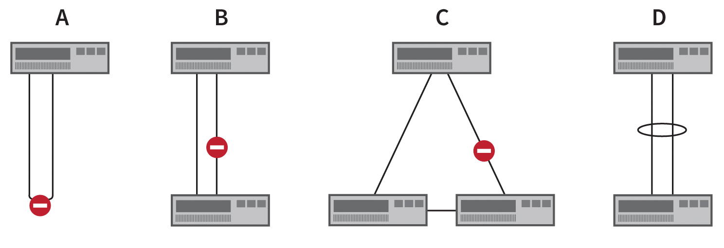
Variant A in Figure 1 offers no technical advantages and usually only arises from carelessness. Variants B and C, however, are often desired in order to increase the bandwidth between two switches (Variant B) or to achieve redundancy in the event of a cable failure caused by external influences – for example, construction work between two buildings – (Variant C). The block by the spanning tree in Variant B initially lifts bandwidth aggregation.
Switch manufacturers have developed different, sometimes mutually incompatible, solutions, such as EtherChannel, Port Channel, virtual PortChannel (Cisco), and Trunk (HP). These technologies bundle multiple physical Ethernet connections to create a single logical connection (variant D in Figure 1).
Spanning Tree perceives this logical connection, say, as a 2Gb connection rather than two separate 1Gb connections and therefore does not block either of the two. Variant C is easy to achieve, but it is not optimized. It would be a good idea to change the physical cabling to replace the triangular connection.
For each VLAN (i.e., logical network segment), a separate spanning tree is computed. The Spanning Tree protocol is primarily known today by its three most popular variants: the Rapid Spanning Tree (RST) protocol, the Rapid per VLAN Spanning Tree (RPVST) protocol, and the Multiple Spanning Tree (MST) protocol; the original Spanning Tree variant suffers from high convergence times in complex topologies, thus leading to failures of 30 to 50 seconds.
The spanning tree table is computed in three main steps:
- Election of the root bridge
- Election of root ports
- Election of the designated ports
A switch port can assume different roles and states (see the box titled "Roles and States of Switch Ports"). The Rapid Spanning Tree variant bundles the states Disabled, Blocking, and Listening as Discarding.
The root bridge is the reference point for the entire spanning tree and computes the paths and settings for the tree. The root bridge is elected on the basis of the Bridge ID, which is composed of three components:
- Bridge priority
- System ID extension
- MAC address
The bridge priority is configurable in steps of 4096. The system ID and the MAC address are not freely selectable; MAC address changes are possible but not recommended. The higher the value of the bridge priority, the less useful the switch is as the root bridge. A switch with a bridge priority of 0 will most likely become the root bridge, unless another switch in the network also has this value.
If more than one switch has the same minimum bridge priority, the system ID extension and the MAC address quickly settle the election of the root bridge. The candidate with the lowest values wins. The system ID extension corresponds to the VLAN number.
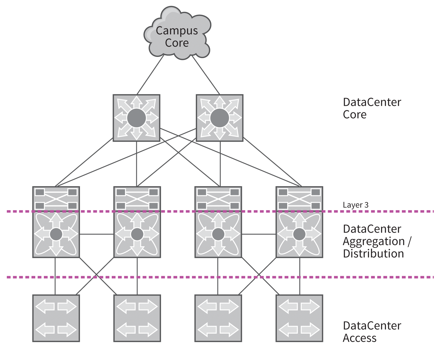
Older switches often have lower MAC addresses than their more recent successors, because many manufacturers assign MAC addresses in ascending order. A lower address leads to the risk of the oldest and potentially weakest switch becoming the root bridge. Because spanning tree calculations are time-consuming on large networks, a powerful switch should take over the role of the root bridge. The vendor design guides recommend setting up the root bridge at aggregation and distribution level, to achieve short convergence times in case of failures (Figure 2).
On Cisco switches, the bridge priority is configured using spanning-tree vlan <VLAN> priority <prior>, or alternatively, with the root bridge macro spanning-tree vlan <VLAN> root [primary **| secondary]. This macro automatically configures the priority based on the current root bridge in the network, but it runs only once when called, rather than permanently in the background.
A Revolt Against the Root Bridge
The exchange of information about the spanning tree topology between different switches is handled by BPDUs (Bridge Protocol Data Unit). Each switch port sends and receives BPDUs. However, this property allows remote attackers to discover and change the topology with forged BPDUs. Countermeasures include BPDU Guards and Filters (see the box titled "BPDU Guards and Filters").
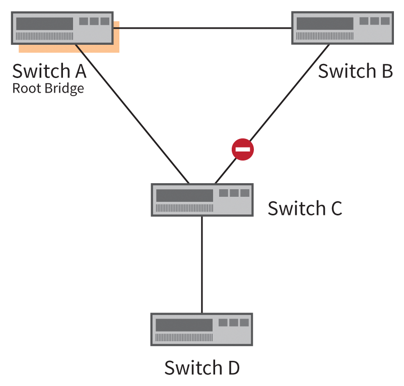
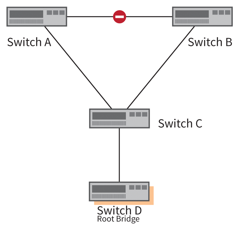
Even after the root bridge is selected, and the entire spanning tree is active, additional switches can join the network. For example, you might wish to install a new horizontal distribution switch. If the new device has a lower bridge priority, it becomes the new root bridge. This change could affect the entire network topology and possibly lead to suboptimal paths and performance bottlenecks.
Protection against accidental or malicious changes to the root bridge are prevented by Root Guard [1]. Figure 3 shows the starting situation in which Switch D is added to the network. If this switch is a lower bridge priority than the previous root bridge, the topology changes, as shown in Figure 4. To prevent this change, configure Root Guard on the port on Switch C that points in the direction of Switch D. Root Guard disables the switch port once it receives a BPDU with too low of a bridge priority.
Cost, Cost, Cost
Connection costs play an important role in choosing the root ports and designated ports. The spanning tree standard costs for different bandwidths are shown in Table 1. However, the predefined values lead to a 40Gb and a 100Gb connection having the same spanning tree cost as a port channel comprising two 10Gb connections, in which the cost is calculated as the total bandwidth of bundled connections. To respond more accurately in such situations, you can configure the spanning tree costs for a connection manually for each port.
Tabelle 1: Connection Costs
|
Bandwidth |
Costs |
|---|---|
|
10 Mbps |
100 |
|
16 Mbps |
62 |
|
100 Mbps |
19 |
|
200 Mbps |
12 |
|
622 Mbps |
6 |
|
1 Gbps |
4 |
|
10 Gbps |
2 |
|
20+ Gbps |
1 |
Figure 5 shows a topology example with four 100Mbps switches, in which Switch 4 becomes the root bridge. Because all of the connections have a speed of 100Mbps, the cost for each port is 19, as shown in Table 1. The only exception is the port channel between Switch 3 and Switch 4, which offers a total of 200Mbps and therefore has a cost value of 12.
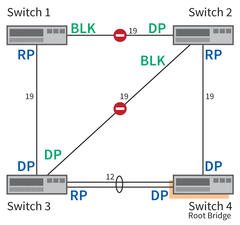
Based on these costs, it follows that the root port on Switch 1 (abbreviated in the figure to RP) points in the direction of Switch 3. The opposite switch port becomes the designated port (abbreviated DP) because the cost is only 31 (19+12) on this path, compared with 38 (19+19) via Switch 2.
If there were a port channel between Switch 3 and Switch 4, two equally expensive routes would lead from Switch 1 to the root bridge (Switch 4). In this case, the bridge IDs would be used to calculate the path, where the lower ID is authoritative.
All switch ports on the root bridge (Switch 4) are designated ports, as well as all ports that are opposite to a root port. In the connection between Switch 1 and Switch 2, the port roles are determined – with the possible options Designated and Blocked – based on the cost of path to the root bridge. For Switch 2, the cost is 19, but Switch 1 has a cost of 31. Thus, the ports between Switch 1 and 2 all become blocked or designated ports. This applies in kind to the connection between Switches 2 and 3: the path cost of Switch 3 to the root bridge is 12; thus, the port pointing in the direction of Switch 2 becomes the designated port.
All of these spanning tree calculations result in blocks between Switches 1 and 2, and between 2 and 3, as shown in Figure 5. Communication between 1 and 2 is therefore routed through Switches 3 and 4.
The topology shown in Figure 5 demonstrates that the location of the root bridge in the network plays an important role. In addition to optimal routes, admins also need to consider the need to recompute the spanning tree in case of switch failures; for optimal speed, the root bridge should be a switch that is as powerful as possible.
More Dangers
In his blog [2], Scott Hogg, the Chief Technology Officer of network technology company GTRI, describes some common errors related to spanning tree configurations. One of these errors relates to the failure to observe size limitations of a spanning tree (i.e., the maximum number of cascaded switches). Ideally, a star topology completely prevents cascaded switches, but implementing a star topology is often impossible, for example, in a campus with multiple buildings.
Another fundamental weakness of Spanning Tree is that the algorithm assumes no switch is connected in the absence of BPDUs on a port. This conclusion is potentially false, however, and incorrect configurations or software errors can thus cause loops in the network.
A possible cause for lack of BPDUs is a hardware error. For fiber optic connections, one of the two channels might be damaged so that the connection can still receive BPDUs but not send them. Unidirectional Link Detection (UDLD) [3] helps to counter these problems in OSI Layer 1. UDLD is complemented by Loop Guard [4].
The false conclusion that no switch is connected because no BPDUs arrive is also countered by Bridge Assurance. The Bridge Assurance technology should therefore be in place on all switch ports that connect to other switches. The exceptions are various forms of multiple-chassis EtherChannels; for example, Bridge Assurance is not recommended for Cisco virtual PortChannels (vPCs).
Then and Now
On older Ethernet networks, a topology as shown in Figure 6 is conceivable. In Figure 6, the spanning tree has disabled half the links in the Layer 2 area, and the server (bottom) uses only one of two connections. The role of the root bridge is handled by the AGG1 switch. In conjunction with AGG2, the switch forms the boundary between Layer 2 and Layer 3; the two are referred to as Layer 3 switches, although – according to the OSI Reference Model – a switch resides in Layer 2. The two Layer 3 switches run a First Hop Redundancy Protocol (FHRP), either with the open VRRP standard or using an alternative such as Cisco's proprietary HSRP counterpart. The protocol is only active on AGG2. The First Hop is the IP default gateway of the server.
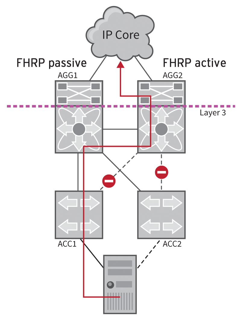
The problem of the suboptimal route that the IP packets take from the server to the gateway (AGG2) in Figure 6 results from a spanning tree blocking connections for all routed packets through AGG1. To fix the problem, either AGG2 would have to take over as the root bridge, or you would need to enable the FHRP protocol on AGG1. In a more complex topology, the impact of such an unfavorably placed root bridge often causes much more serious problems.
Non-Blocking Architecture
Because of high port prices and performance requirements for datacenter switches, it is generally not a good idea to use a spanning tree to block links. Various manufacturers offer remedies that allow multiple physical links between two switches, or between a switch and a server, to be combined to form a logical link (Figure 7). Some solutions even allow the combination of more than two switches.
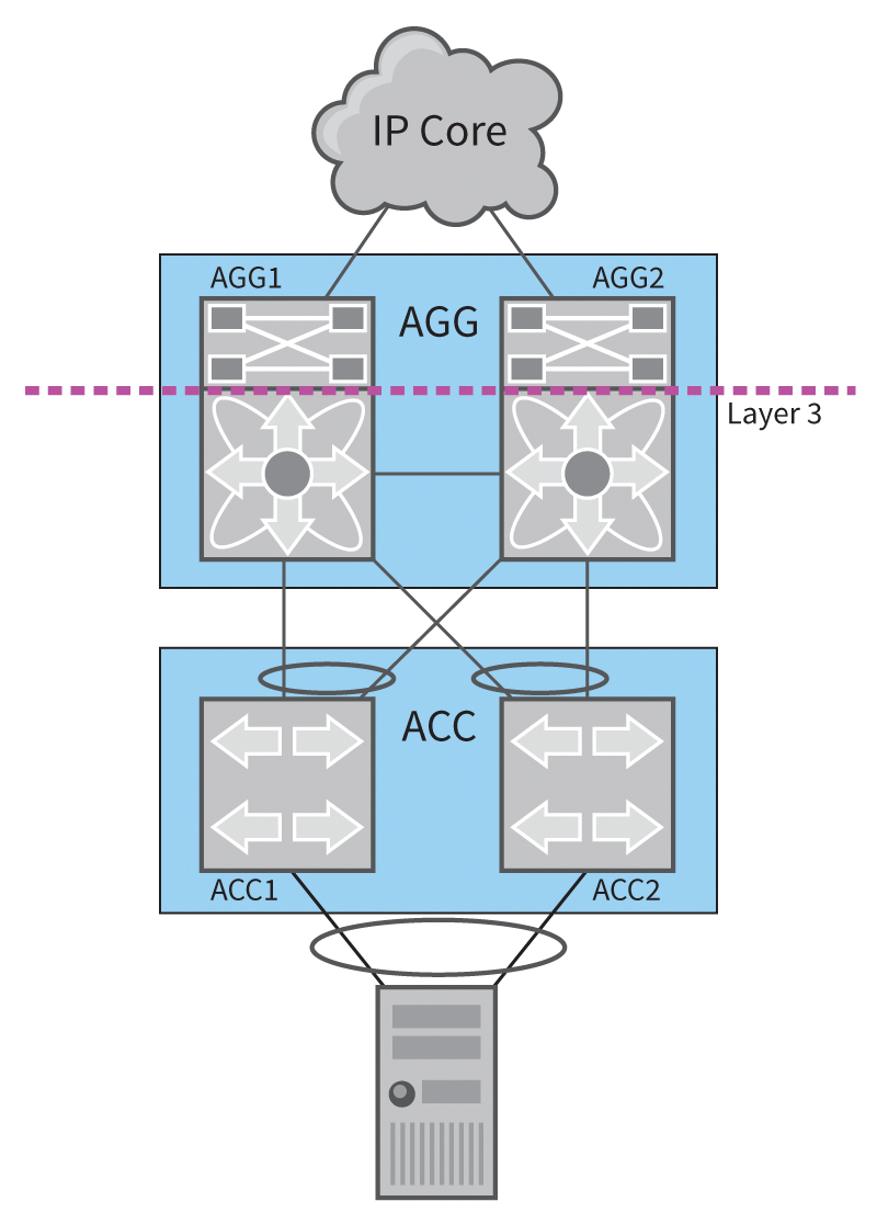
The aggregation switches AGG1 and AGG2 in Figure 7 now create a big AGG switch, and the two access switches ACC1 and ACC2 form the logical ACC switch. Solutions such as Multiple-chassis EtherChannel, for example, support this kind of aggregation. The server operating system, in turn, bundles the two connections to ACC1 and ACC2 to create one logical link (network bonding) so that the full bandwidth is available.
Scalability of Layer 2
The topology shown in Figure 7 scales well, but some new challenges arise in large networks because of the possibilities of virtualization. Figure 8 shows a sample topology. Rack 1 and Rack 2 use the same VLAN, which enables the migration of a virtual machine from Rack 1 to Rack 2 on the fly using a tool such as vMotion by VMware. However, often there is only one VLAN available per rack to keep the broadcast domain small, despite a large number of virtual machines – as is the case with Racks 3 and 4.

In addition to the restriction on the mobility of virtual machines in multiple-chassis EtherChannel, the restriction to two pairs of switches is a limiting factor. Added to this are the long convergence times for Spanning Tree – if several hundred VLANs are in use – recomputing the spanning tree if the root bridge fails still takes some time.
To address these challenges, some proprietary protocols allow topologies as shown in Figure 9. The foundation for this approach was laid down by the official IETF Trill (Transparent Interconnection of Lots of Links) standard. The Trill standard allows Equal Cost Multipathing in Layer 2 networks.
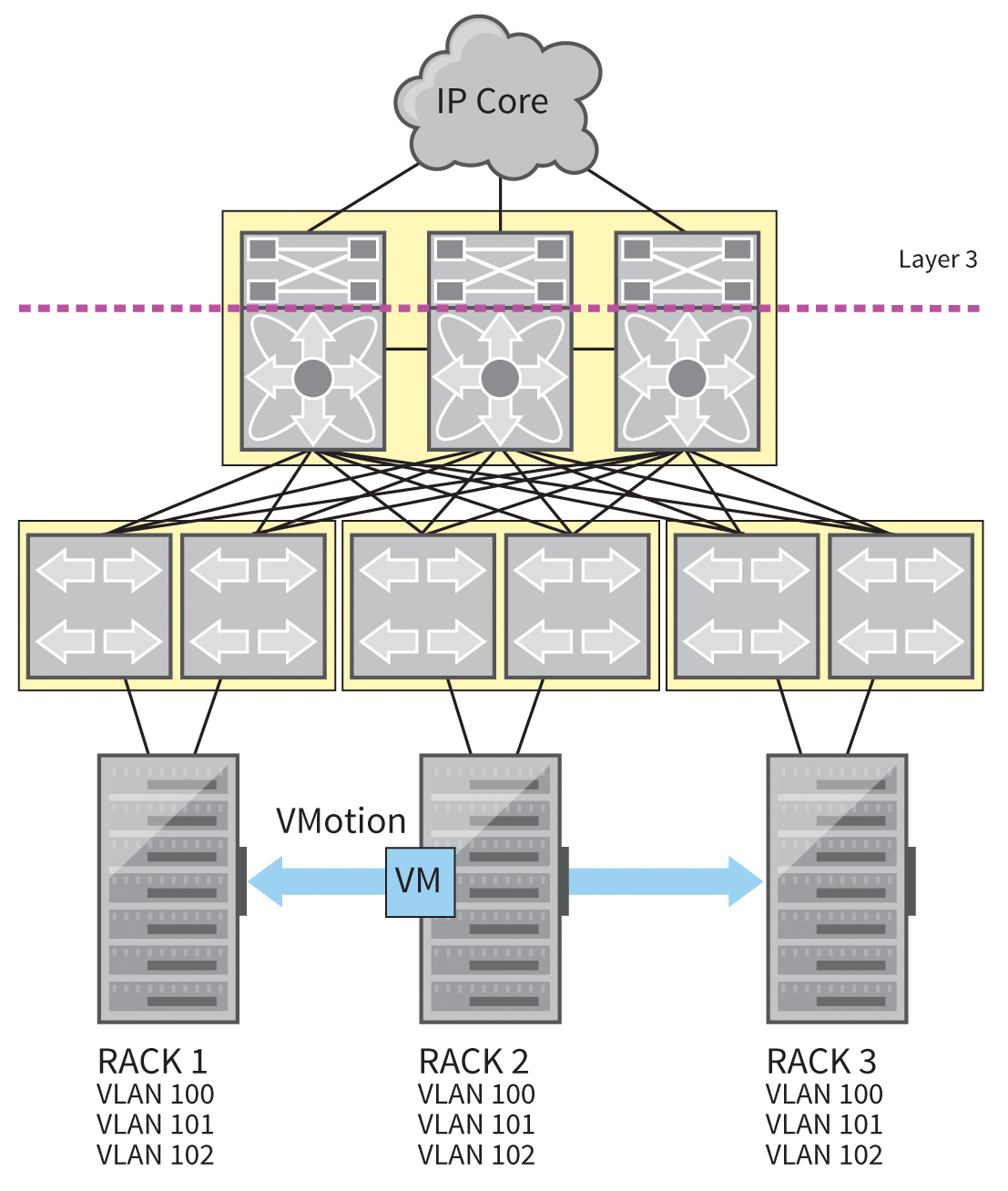
Cisco FabricPath is also based on Trill but offers advanced options. For example, in FabricPath, each switch only learns the MAC addresses that it really needs – on classic Layer 2 networks and Trill, however, each switch stores all the MAC addresses. The scaled address tables in FabricPath result in better performance and avoid switches hitting the memory limits of their hardware.
All connections between the switches in Figure 9 can be operated with Cisco devices in FabricPath mode, which is activated through the switchport mode fabricpath command. The Fabric Shortest Path First protocol handles Layer 2 routing, with IS-IS (Intermediate System to Intermediate System) in the background. The influence of the spanning tree ends at this point – the connection is no longer about Ethernet connections but about FabricPath. However, connections to classical Ethernet switches are still possible.
Conclusions
The Spanning Tree protocol is a fundamental part of an Ethernet network. If you manage an Ethernet network with multiple switches, a good understanding of Spanning Tree will help you ensure stability and optimize performance.
