Understanding the Spanning Tree protocol family
Switch Keeper
The Spanning Tree protocol, which was designed to provide a loop-free Ethernet network topology, has been around for more than 30 years and has been through many iterations. The various versions include the conventional Spanning Tree protocol, Per-VLAN Spanning Tree protocol, Rapid Spanning Tree protocol, and a more recent version known as the Multiple Spanning Tree protocol. This introduction to Spanning Tree looks at some of the important enhancements introduced with later variants.
Broadcast Storm
Ethernet uses a multiaccess broadcast technique. A switch spreads the broadcast message all over the network to make sure all hosts can receive the message. To accomplish the task, when the switch receives a broadcast, it duplicates the message to all ports except the port that sends the broadcast.
In Figure 1, PC1 generates broadcast traffic. When SW1 receives the traffic, it duplicates to all other ports. SW2 does the same thing, so that all hosts in the network receive the broadcast message. This mechanism works perfectly in a simple network that does not have a loop connection.

A loop connection complicates the simple scenario depicted in Figure 1. In Figure 2, when SW1 receives a broadcast, it duplicates the message to SW2. SW2 receives the message and sends it to SW3. When SW3 receives the message, it duplicates it back to SW1, and the process repeats forever. This phenomenon is called a broadcast storm, which can consume all available CPU resources and network bandwidth. The entire network could be unavailable in several seconds after a broadcast storm occurs.

Spanning Tree Protocol
The Spanning Tree protocol (STP) is designed to eliminate the loop by blocking some links in the network. STP can define the port role and control the state of the switch ports. By moving the port from the forward state to the blocking state or vice versa, the paths between switches can be closed or opened. Decisions about which paths to open or close are made using the Spanning Tree Algorithm (STA). STP will choose a switch to be the root switch automatically. (It is also possible to choose the root switch manually through configuration.) After a root switch is chosen, all non-root switches should only have one path to reach the root switch.
If more than one path exists, all paths should be blocked except the best one. The best path is the path that has the lowest root cost. Root cost is a relative measure of the bandwidth of all linkages the message needs to pass through before reaching the root switch. Higher bandwidth linkages have lower costs. You can customize the root cost on each port to override the automatically calculated value in order to choose which path to use as the active path. The blocked paths become standby connections and will be awakened if the original root path is disconnected.
In Figure 3, SW1 is configured to be the root switch. SW3 has two paths to reach the root switch, left and right. The right path is blocked because of its higher root path cost.

Topology Change
When a network port on a switch goes from DOWN to UP, the physical connection may become totally different. Any change to an existing network, such as adding a new switch, could cause looping. On the other hand, if a port goes from UP to DOWN, a link between the switches may be disconnected and cause the switch to lose the original root path. So, switches will keep track of the root path cost of each port. Changes to the physical connection will change the root path cost, and STP needs to change the network topology.
Per-VLAN Spanning Tree
In Figure 3, blocking the linkage between SW2 and SW3 solves the looping issue, but it also wastes bandwidth. The standby link is only used when the active link fails. Is there any method that will allow a more efficient use of bandwidth? The answer is Per-VLAN Spanning Tree (PVST) [1].
A virtual LAN (VLAN) configuration is common on many modern networks. Cisco's proprietary protocol, PVST, runs separate STP processes for each VLAN so that every VLAN has a different network topology. PVST is the default spanning tree mode for Cisco switches. You can choose which switch to use as the root switch and tune the root cost on each port. Thanks to PVST, you can choose a different root switch, as well as assign a different root cost, for each VLAN in order to create different network topologies for the VLANs.
Listing 1 shows the basic Cisco PVST configuration for the topology shown in Figure 4.
Listing 1: A Basic PVST Configuration
SW1(config)#spanning-tree vlan 10 root primary
SW2(config)#spanning-tree vlan 20 root primary
SW3(config)#interface fastEthernet 0/1
SW3(config-if)#spanning-tree vlan 20 cost 999
SW3(config-if)#interface fastEthernet 0/2
SW3(config-if)#spanning-tree vlan 10 cost 999

Because the traffic volumes are not always equal for the different VLANs, network traffic is not always equally load balanced through the two linkages, although at least both links are used instead of just one.
Convergence Time
The time period from when the topology changes until the network becomes stable again is called the convergence time. The convergence time can be from 30 to 50 seconds for STP and PVST, which means that if the network experiences changes in topology, STP needs up to 50 seconds to renew the network topology. Some of the network users might have a service interruption for up to 50 seconds, which is terribly long and not acceptable for a modern network. Cisco enhances PVST by adding features such as Backbone fast, UplinkFast, and PortFast [2] to shorten or eliminate the convergence time. However, these enhancements only help for the case of existing linkages going DOWN. Time for convergence is still necessary when adding new switches to the network.
Rapid Spanning Tree Protocol
To shorten the convergence time, Cisco released a proprietary protocol called Rapid Spanning Tree Protocol (RSTP, or Rapid-PVST in a Cisco configuration) [3]. RSTP inherits PVST's Backbone fast, UplinkFast, and PortFast features, and it also adds a synchronization process to speed up the convergence. Earlier protocols such as STP and PVST send Hello packets every two seconds to the neighbors to keep alive and exchange the network topology information.
When a topology change occurs, switches notify others and spread the information one by one when sending the next Hello message. In other words, switches wait to be notified passively after a change.
For RSTP, the function of Hello messages changes from notification to negotiation. When the topology changes, switches where the change occurs use Hello messages to communicate actively and immediately. The switches negotiate and decide the linkage state (Should it be forwarded or blocked?) in a very short time. After that, the second switch negotiates with the third switch, and so on. All switches in the network receive the topology change request and complete the convergence in a few hundred milliseconds (according Cisco).
Only a simple command is needed to migrate a Cisco device from PVST to RSTP:
SW1(config)#spanning-tree mode rapid-pvst
RSTP is backward compatible with PVST, which means you can migrate the switches on your network to RSTP one by one.
Multiple Spanning Tree Protocol
Because RSTP is a Cisco proprietary protocol, switches from other vendors cannot enjoy the speedy convergence provided by RSTP. Luckily, an open standard called Multiple Spanning Tree Protocol (MSTP, or MST in a Cisco configuration) [4] serves a similar role. MSTP inherits the fast convergence features of RSTP and includes features to reduce resource usage.
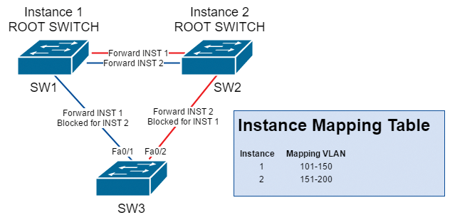
RSTP works very well if there are only a small number of VLANs. However, when the number of VLANs increases, switches need to handle a lot of network topologies simultaneously. CPU resources and bandwidth utilization are used for STA calculations and protocol communication. Moreover, most of these topologies are actually the same! It does not make sense to spend resources to maintain lots of identical topologies for different VLANs. Figure 5 shows 100 VLANs from VLAN 101 to VLAN 200. A total of 100 Spanning Tree topologies are running on the switches, but the topologies of VLAN 101-150 are actually identical, as are VLANs 151-200.

MSTP can group the VLANs into instances using a mapping table. Each instance will have its own network topology that will apply to all VLANs that are mapped to the instance. For example, for the network in Figure 5, VLAN 101 to 150 can be grouped into instance 1 and VLAN 151 to 200 can be grouped into instance 2 (Figure 6). The total number of network topologies is then decreased from 100 to 2.

Listing 2 shows the MSTP mapping table configuration, which should be repeated on all switches.
Listing 2: MSTP Mapping
SW1(config)#spanning-tree mst configuration
SW1(config-mst)#name Region1
SW1(config-mst)#revision 1
SW1(config-mst)#instance 1 vlan 101-150
SW1(config-mst)#instance 2 vlan 151-200
Then, enable MSTP on all switches using the command:
SW1(config)#spanning-tree mode mst
Next, set SW1 to be the root switch of instance 1 and set SW2 to be the root switch of instance 2:
SW1(config)#spanning-tree mst 1 root primary
SW2(config)#spanning-tree mst 2 root primary
Finally, tune the spanning tree cost on SW3, as shown in Listing 3.
Listing 3: Tuning the Spanning Tree Cost
SW3(config)#interface fastEthernet 0/1
SW3(config-if)#spanning-tree mst 2 cost 999
SW3(config-if)#interface fastEthernet 0/2
SW3(config-if)#spanning-tree mst 1 cost 999
Region
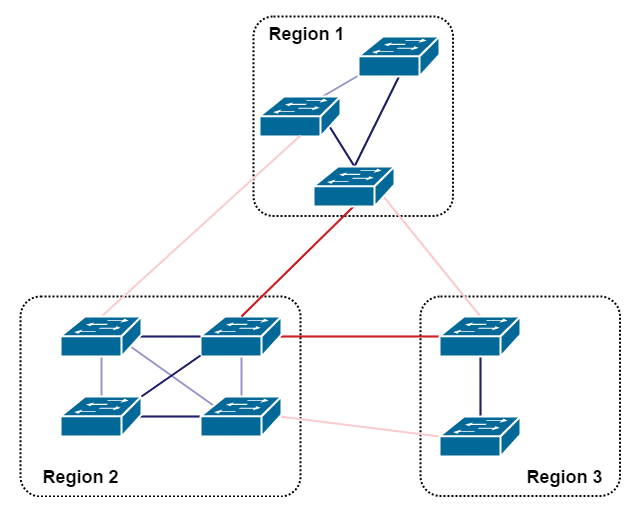
The concept of a region is another revolution of MSTP. You can split the entire network topology into different regions for easy management. Each region has its own instance topologies and does not influence other regions. The interconnection of regions is handled by the Common and Internal Spanning Tree (CIST). In CIST's view, each region is treated as a big virtual switch. The STA will be run on those big virtual switches to determine the state of the interregion connected ports.
In Figure 7, the network is grouped into three regions. The concept is similar to the autonomous system (AS) number used with the border gateway protocol (BGP). Each region has its own network topology. When the topology changes in a region, the change only occurs inside that region and does not influence other regions.

Conclusion
Modern networks don't just transmit data but also provide voice service and even support emergency and security components such as CCTV, access control, and fire protection. High availability and resiliency are essential in today's network infrastructure. Even small intervals of downtime can create big problems. If you find some switches on your network that are still running conventional STP or PVST, it is a good idea to check the feasibility of migrating to RSTP or MSTP.
